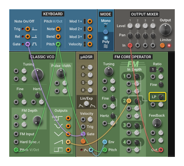
FM Core Operator
Audio Generators
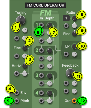
- Tuning Knob Sets the reference frequency when the Pitch input is at 0V. Double-click for middle C.
- Fine Knob ±1 semitone adjustment around tuning frequency.
- Hertz Knob ±5 Hz adjustment around tuning frequency.
- Env Input Envelope signal input to control output volume. Normalled to 10V (unity gain).
- Pitch Input Calibrated for 1V/octave pitch signals.
- FM Inputs 4 independent audio-rate FM inputs. Connect them to other FM Core Operator outputs, or to different audio sources.
- FM Depth Knobs Adjust the amplitude of the FM input signals.
- Ratio Knob Operator frequency multiplier.
- Fine Knob Fine-tunes the frequency multiplier.
- LP Knob (FM 2) Controls the cutoff frequency of a low-pass filter on the FM 2 input.
- FB Knob Controls the amount of FM feedback. It has the effect of changing the operator waveform from sine to sawtooth-like to white noise.
- Oscillator Output Output signal.
Overview ⚓︎
The FM Core Operator module is a building block used in the creation of complex digital FM patches.
Before going any further, make sure to familiarize yourself with the Superficial Introduction to FM section in the 3-operator Digital FM manual. We will not repeat that information here.
The FM Core Operator module is essentially the sound generation section of a single operator in the 3-operator Digital FM module, but with more modulation options.
The FM Core Operator and 3-Operator Digital FM modules use the synthesis technique found in popular FM synthesizers, PC sound cards, and game console chips of the 1980s and early 1990s. Although this method became known as FM, it is technically implemented as phase modulation rather than frequency modulation. To distinguish it from the Classic VCO’s true FM while preserving the familiar terminology, we refer to it as digital FM.
Usage ⚓︎
Tuning ⚓︎
The tuning of the module is controlled with the Tuning, Fine and Hertz knobs, and a 1V/octave pitch signal can be connected to the Pitch input to follow notes from the Keyboard module or from a sequencer. See Oscillator Tuning for more information.
Basic FM ⚓︎
Building a digital FM patch requires at least two FM Core Operator modules, with the output of the first connected to the second.
The following patch shows the most basic FM generator. Build it and try adjusting the Ratio knob on either module and the FM 1 Depth knob on the second operator to get different timbres. Make sure that the patch is in Mono mode.

The module on the left is called the modulator, since it modulates the frequency of another operator, and the one on the right is the carrier because it carries the audio signal we hear.
Set both Ratio knobs back to 1 (this is the default value if you double-click on the knob) and the FM depth around 25% (centered).
We will now make the patch follow keyboard notes by double-clicking on the Pitch input on each module to automatically connect it to the Keyboard Pitch output.
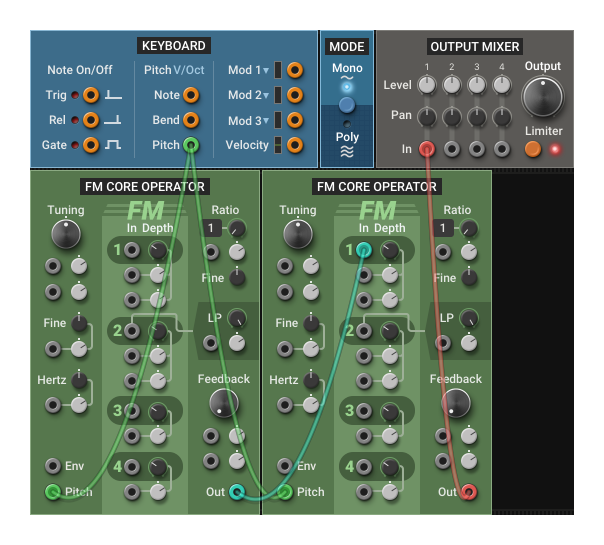
In an FM patch, if you want a harmonic result, all operators should follow the same pitch. Try disconnecting one of the pitch inputs and playing different notes: you should hear dissonant tones. This is a good starting point for percussive patches or complex sound textures.
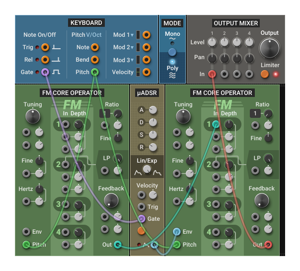
We will now turn this patch into a proper instrument by adding an amplitude envelope so the sound stops when the note is released.
First, make sure both Pitch inputs are connected to the Keyboard Pitch.
Then, let’s take advantage of the Env input at the bottom left of the module. This input drives an integrated VCA that controls the output volume. By default, the output oscillates between -5V and +5V. However, if an envelope signal is present on the Env input, the output volume will follow it: at 0V the module will be silent, and at 10V it will play at normal volume.
Add an envelope module to the patch (we used a µADSR here because of space constraints, but any other envelope will do), connect its Gate input to the Keyboard Gate output, and connect its main output to the Env input on the second FM Core Operator.
At this point, you can make the patch polyphonic by clicking on the button in the Mode module.
Finally, we will make the timbre evolve while the note is playing. As we saw earlier, in an FM patch the timbre varies when the ratio between the operators changes or when the modulation depth changes. In a basic FM patch, we are interested in the latter.
There are two ways to change by how much the modulator affects the carrier:
- Change the output volume of the modulator
- Change the FM input depth on the carrier
The first option simply involves connecting an envelope generator to the first operator’s Env input. This is what happens internally in the 3-operator Digital FM module: each operator has a built-in ADSR that controls its volume, and the output volume knob controls how much of that signal goes to the carrier. If you try this, you may want to increase the FM Depth on the carrier for a more pronounced effect.
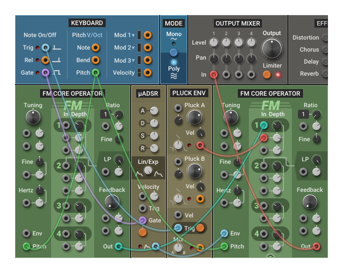
The second option is a bit more complex but gives more flexibility: you connect the envelope generator to an FM Depth modulation input on the carrier.
You can try this by adding a Pluck Envelope, connecting its Trig input to the Keyboard Trig and its Pluck A output to the first FM Depth modulation input on the carrier.
Play with the Pluck A knob, the FM Depth knob and the attenuverter next to the modulation input to get a feel of the different sounds you can create. With this technique, you get independent control over the base amount of modulation (FM Depth) and over the amount of change (modulation attenuverter).
Complex FM Patches ⚓︎
To create complex digital FM patches, simply reproduce the concepts of the previous sections with more than two FM Core Operator modules. You can connect up to 4 modulators in parallel to a single carrier by using the carrier’s 4 FM inputs. You can also chain many operators in series to produce brighter and harsher FM timbres.
Here are a few simple guidelines you can follow. They are not absolute rules, but they are generally a good starting point:
- For tuned instruments, all operators should have their Pitch input connected to the same source.
- At least one carrier should be set to the default tuning (all tuning knobs centered) with its Ratio set to 1. This will be the perceived pitch of the patch (barring some weird FM modulation source).
- Carriers should have an envelope connected to their Env input.
- Modulators don’t need an envelope, but adding one will make the patch more expressive.
- Vibrato can be achieved by connecting a LFO to the Tuning—Fine modulation input:
- For a simple synth-like vibrato, connect the LFO to all FM Core Operator modules and use the same modulation depth.
- For a more complex, chorus-like effect, don’t connect the LFO to all modules.
- If the sound is too static, consider slightly detuning a modulator with the Tuning—Fine knob by a few cents, or with the Hertz knob by less than 0.50 Hz.
- For more dissonant sounds, use the Ratio—Fine knob. It covers the fractional ratios above and below the current ratio (e.g. for a ratio of 5, the range of the Ratio—Fine knob is 4 to 6).
You will find many of these concepts in the Basics—Digital FM Pad patch in the Multiphonics CV-3 library.
Feedback ⚓︎
On its own, the FM Core Operator produces a pure sine wave.
Feedback lets the operator modulate itself to produce a richer tone: its own output is fed back into its FM input. At low feedback amounts, the sine wave gradually turns into a brighter, harmonically rich, sawtooth-like waveform. As you further increase the feedback, the waveform becomes more chaotic, losing a clear pitch and approaching noise.
Because the module derives the feedback signal from its own output, any envelope patched into the Env input will also affect the amount of feedback. If the envelope reduces the output level, the feedback will be weaker; if it boosts the level, the feedback effect will be stronger.
Input 2 Low-pass Filter ⚓︎
Input 2 is different from the others: its signal passes through a 12 dB/octave low-pass filter, with its cutoff frequency controlled by the LP knob. This has two purposes: making hybrid FM patches possible with arbitrary modulator signals and taming bright modulators in pure digital FM patches.
Using Input 2 in Hybrid FM Patches
In the FM Core Operator module, the FM inputs work optimally with two kinds of sources:
- Other FM Core Operator modules
- The 3‑operator Digital FM module
If you connect an FM input to a typical analog waveform like a sawtooth or a rectangular pulse from a Classic VCO, you might hear a harsh, high‑frequency buzz. That’s because the so-called digital FM synthesis used in this module is actually phase modulation, which doesn’t react well to the abrupt discontinuities that are common in analog waveforms.
Since so much of what makes modular synthesis enjoyable is connecting things that are not meant to be connected together, we wanted to make hybrid analog/digital FM patches possible.
If you want to use an analog oscillator or an otherwise bright signal as an FM source, connect it to FM input 2 and adjust the LP knob until you like how it sounds.
Using Input 2 for Complex FM Signals
Complex FM signals generated from multiple modulators in series can make the carrier sound harsh, especially when playing higher notes. It can be a good idea to connect such signals to the carrier’s FM input 2 to take advantage of the low-pass filter. Setting the LP frequency between 1000 Hz and 5000 Hz will make the upper register more mellow while keeping a rich sound for lower notes.