8-segment Envelope
CV Generators
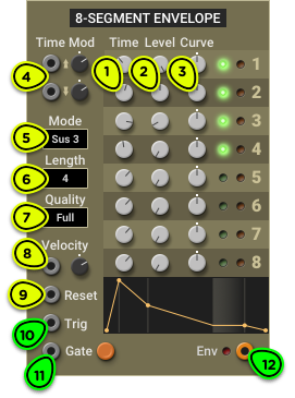
- Time Knobs Sets the duration of each segment.
- Level Knobs Sets the target level of each segment.
- Curve Knobs Sets the curve of each segment.
- Time Mod Inputs One modulation input for all rising segments, and one for all falling segments.
- Mode Selector Sets the envelope behaviour when a gate is present. Full runs from start to finish; Loop loops over active segments; Sus 1 to Sus 8 sustains at the end of the chosen segment.
- Length Selector Sets the number of active segments in the envelope.
- Quality Selector Sets the envelope quantization to simulate a digital envelope generator using a DAC with that number of bits.
- Velocity Input Amplitude modulation input, designed to be connected to the Keyboard Velocity output. Modulation depth can be adjusted with the knob.
- Reset Input When triggered, immediately stops the envelope generator and sets its output to 0V.
- Trig Input When triggered, restarts the envelope generator from the attack segment.
- Gate Input Main input. A rising edge starts the envelope, and a high gate keeps it looping or sustained depending on the selected mode.
- Env Output Envelope signal output.
Overview ⚓︎
The 8-segment Envelope module generates complex envelope signals composed of up to 8 segments. While the ADSR module reproduces the typical characteristics of an analog envelope generator, the 8-segment Envelope draws inspiration from the digital envelope generators found in synthesizers of the 1980s and 1990s.
The segments run sequentially starting from the first one when a trigger or gate signal is detected on the Trig or Gate input.
Each segment has a duration, a target level and a curve (Time, Level and Curve knobs respectively). The first segment always starts from 0V, and the output will always fall back down to 0V at the end of the last segment.
The number of active segments can be set with the Length selector. The green LEDs to the right of the segment knobs let you know which segments are active.

There are three main modes of operation that change how the module responds to the Trig and Gate inputs, selected from the Mode selector: Full, Loop, and Sus 1 to Sus 8 (sustained). They are explained in the next section.
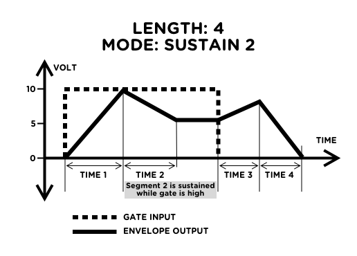
A representation of the shape of the envelope is displayed below the segment controls. In sustained mode, the shaded area represents the level at which the envelope holds while the gate is high.
The graphic display of the envelope is not a perfectly proportional representation of its actual output. It was designed to help visualize the shape of the envelope within the size constraints of the module. Very short segments are made long enough so that they are clearly visible, and very long segments are made shorter to avoid having a single long segment overtake the whole display. Use an Oscilloscope in roll mode for an exact visualization of the envelope.
Modes of Operation ⚓︎
The Mode selector lets you change how the module responds to gate and trigger signals on the Gate and Trig inputs.
Full Mode ⚓︎
In Full mode, the envelope is free-running. It starts whenever a trigger is detected on the Trig or Gate input and always runs from start to finish, regardless of which input is used.
The envelope stops instantly when a trigger signal is detected on the Reset input.
If the envelope is retriggered while it is already running, it restarts from its current level rather than from 0V. If you want it to restart from 0V, connect the trigger signal to both the Trig and Reset inputs.
Loop Mode ⚓︎
In Loop mode, the envelope loops from its first to its last segment. This turns the envelope into a custom LFO.
If the envelope is triggered only from the Trig input with no signal on the Gate input, it will loop endlessly.
If the envelope is triggered from the Gate input, it will loop for as long as the gate is high. When the gate goes down, it will run to the end of the last segment and stop.
If the Reset input is triggered, the envelope stops instantly.
Internally, the envelope runs at CV rate, not audio rate. This means that although an envelope in loop mode can replace an LFO, it will not be usable as a substitute for an audio-rate oscillator.
Sus 1 to Sus 8 Modes ⚓︎
In sustain mode, the envelope holds its output level at the end of the sustain segment for as long as the gate remains high.
While the gate is high, the envelope can be retriggered from the start with the Trig input. It does not restart from 0V; it begins the first segment from its current value. Unlike in Full or Loop mode, the envelope does not start from the Trig input alone; it needs a Gate input.
The envelope stops instantly when the Reset input is triggered. If this happens while the gate is high, the envelope immediately restarts from 0V.
Modulations ⚓︎
Velocity Input: Amplitude Modulation ⚓︎
The Velocity input allows a CV signal to modulate the amplitude of the envelope according to the rules described in Understanding Signals—Velocity.
When the Keyboard module provides the gate or trigger signals that start the 8-segment Envelope, the patch can be made velocity sensitive by connecting the Keyboard Velocity output to this module’s Velocity input. You can then adjust the sensitivity with the knob.
In patches that don’t need a velocity sensitive envelope, you can use the input as a general-purpose amplitude modulation input. For example, connecting it to a LFO will produce a tremolo effect that follows the envelope level.
Time Modulation ⚓︎
The two Time Mod inputs let you control the segment lengths from any CV signal.
The top input, with an upwards-pointing arrow, controls the duration of segments with a positive slope.
The bottom input, with a downwards-pointing arrow, controls the duration of segments with a negative slope.
Quantization ⚓︎
In the 1980s, most synthesizer manufacturers switched to digital envelope generators (DEG). Due to their digital nature, these envelope generators don’t have a smooth output like their analog counterparts. This characteristic can be reproduced by choosing a lower bit depth from the Quality list.
At “Full” quality, the module runs at 32-bit floating point like all other Multiphonics modules. When any other bit depth is selected, quantization will be applied. Using a low bit depth envelope will add some grit to FM or filter cutoff sweeps.
The quantization algorithm simulates a digital envelope generator that uses an N-bit counter to cover the range from 0V to 10V. Knowing that an N-bit integer can represent values from 0 to 2N-1, it follows that a 3-bit envelope generates 8 distinct values: 0, 1, 2, 3, 4, 5, 6 and 7. In the module output, these values are spread equally between 0V to 10V, as shown here:
